
The PIC Furby was one of my last year college projects I did for my CTEC1630 Embedded Systems Design class (November 2000) towards my diploma for Computer Engineering Technology COOP for Niagara College, in Welland Ontario. I make it available online because I still get inquiries about it. The technology is super old… I mean, it was really old when I was taking it up in class. Now-a-days, I have seen some websites talking hacking Furbies using Bluetooth. How cool is that?! Ok, so the technology is old, still is educational though, and very fun to play around with. So… enjoy!
About the Programable Interface Controlled Furby™
Abstract
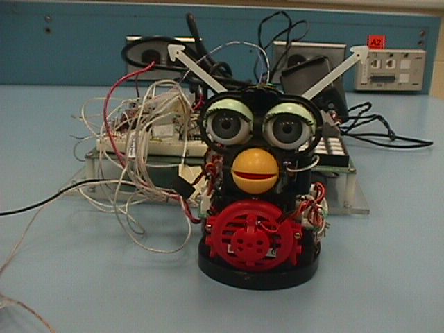
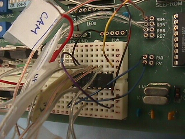
The project consists of a Furby™ toy whose microprocessors were removed and replaced with PIC16F84 chip on a PIC prototype board.
The toys moves once a command is received via RS-232 communication or one of the toy’s sensors being pressed. The prototype board has a MAX232 driver chip with self-contained charge pump, which generates the positive and negative voltages required for the RS-232 interface. The RS-232 specifics are 2400-baud rate; no parity, and one stop bit.
The single-chip PIC micro-controller functions as software UART, receiving a single serial ASCII character that is then interpret as a command for toy’s new micro-controller to execute. A shift register is used to take in sensors information form the toy. This shift register is hooked up to the PIC micro-controller where it deciphers the inputs.
The user may view the toys’ movements by pressing pre-defined characters or using the menu features on the front-end c++ software. Also, by pressing sensors on the toy, more movements and wav files are executed. For example, press ‘t’ on the computer keyboard will result in a wav file being played and the character “t” sent to the toy via RS-232 standards. When the “t” is received, the Talking function will be called and executed; and then the toy will reset in preparation for the next command.
Hardware Design
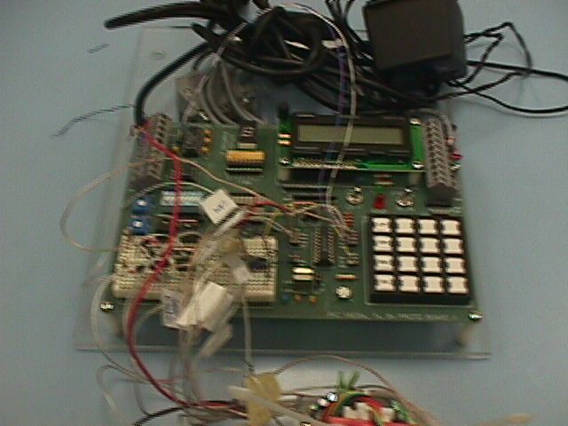
Equipment needed: one Furby(TM) toy; one 74HC165 shift register, one PIC Prototype board. (If a PIC Prototype board is unavailable: PIC16F84, MAX232.)
PIC16F84 is a 18-pin Flash/EEPROM 8-Bit Micro-controller which is used to run the toy. The shift register is used for data acquisition of the toy’s sensors and the MAX232 is used to send and receive information via RS-232 standard communication.
Software Design
In the PIC software design, there are three main parts: UART software, Motor Movement and Data Acquisition. There is also a front end C++ program that I made to use as a user friendly interface to the toy. The software is half put together (but works) and could really use some sprucing up. A project for another time.
The UART software allows me to send and receive information from the computer to the PIC via the computer’s COM Port using RS-232 communication standards.
A series of Function Calls/Methods were used to make the motor move forward or in reverse. The FORWARD and REVERSE function calls made sure that only one output is set on and the other output is set off at any one time. These function calls are called by MOVE_FORWARD and MOVE_BACKWARDS which is used to set how long the motors stay on in the direction needed.
To capture inputs from the toy itself, a shift Register (74HC165 chip) was used for the hardware for data acquisition. Through software, you are able to clock in each bit when needed.
Programable Interface Controlled Furby™ Resources
Feel free to download the following files and try your hand at making it and better yet improving the project. Please give credit where due. Please tell me what you do with the downloads; I would love to hear about it. Please have fun with it!
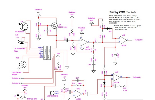
Furby™ Schematic (Original / PDF) – This file was created by Chris Brown and was available for download on HackFurby.com (the website no longer exists).
Furby™ Schematic (Using a PIC16F84 chip / PDF) – Here is a schematic of a toy Furby™ using a PIC16F84 chip instead of its original microprocessor. >> PDF File.
Furby™ Schematic (Using a PIC16F84 chip / CCT file) – Here is a schematic of a toy Furby™ using a PIC16F84 chip instead of its original microprocessor. DesignWorks 4.0 file format, if you happen to have access to this software anymore.
PIC16F84 Datasheet – Datasheet to the PIC16F84 chip used in the project.
74HC165 Datasheet – At the beginning of the project, I could not find a datasheet or much information on the PIC16F84 chip and I had used this database which is very close to the chip I was using. Obviously after I found or got a hold of the correct datasheet I stopped using it. It is still important to reference it because I had heavily used it in the project.
MPASM Assembler Source Code, version 8 (ASM file) – Here is the source code I wrote to control the Furby™ toy using a PIC16F84 chip. In its original ASM file format.
MPASM Assembler Source Code, version 8 (Text file) – Here is the source code I wrote to control the Furby™ toy using a PIC16F84 chip. In a text file so you can easily read it online.
MPASM Assembler Source Code, version 8 (PDF file) – Here is the source code I wrote to control the Furby™ toy using a PIC16F84 chip. In a PDF file so you can easily read it online.
Windows Application – Here is compiler code to re-create the Windows front-end application written in C++ programming language. Zipped file.
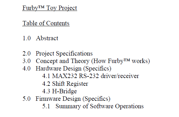
Project Report – This is a comprehensive report on the project including codes and detailed descriptions about the project.
Talking about the Furby™ Project…
Thank you to all those who have reached out to me to let me know how they have used my project, if they had any success using it, and so on. It is nice when I find mentions of my project online. Here are a few things I have found…
Online Mentions
2003 – My project and I were mentioned on the Computer Engineering Technology COOP program page on Niagara College website.
2003 – My project and I were mentioned on the CTEC1630 Embedded Systems Design course page on Niagara College website.
Aug 2016 – I found a TEXT copy of my ASM code for the Furby™ project on www.todopic.com.ar. At the time, it appeared as though my code on been on their website for a while.
Thank you
Thank you to all my classmates/friends who helped me with my project. Thank you for the teachers who helped me figure things out. Specially to the Electrical teacher who helped me understand the motor which was technically outside the scope of the Electronics/Computer college project. And, thank you to my family who continue to put up with me.
All the images with electronics and Furby™ inners are mine. All adorable Furby™ images you see on this website are by Alexas_Fotos-686414 of Pixabay who has allowed his/her Furby™ images to be Public Domain so I could use them. No attribution was required but the photos are so nice I simply had to make mention!
Feedback
“I’ve been looking at your Furby project quite intensively because I’m doing a project for my son for school including a Furby Mod. Thanks for the wealth of information that is available on your site.” Gregory
“Thanks for sharing. Your code really helped me with my school project.” Paul
“Nice project.” Michael
“It is really nice of you to share your code.” Joe
“So much information – thanks!” Harold
“Thanks so much for sharing your hard work. I really appreciate you being open about your project. It look like you had a lot of fun.” Sean


Thank you for visiting. I hope you enjoyed it and found it useful. If you need more information or have a question, or you would like to drop me a line with a comment or with your feedback, don’t hesitate to contact me.